In the last lesson we learned about binary numbers, which are the way computers understand numbers. The next thing we will now study is how we can build simple hardware to add numbers. Once we can add numbers, we can do any math operation, like subtraction, multiplication and division that will be covered later.
Being able to do math is one of the most important things computers do all the time. Examples include calculating where to place a dot on the screen, or figuring out how much memory is available to store something. It is used in just about every computer activity.
Logic Gates / Adders
We will start with the most basic piece of hardware needed, which is called an adder. As you can probably guess, it adds numbers. Of course, the numbers will all be represented as 1’s and 0’s (binary), since that is all computers can understand. The adder will be built using Logic Gates. Logic Gates do logical operations. An AND Gate only gives a ‘1’ output when all the inputs are ‘1’. An OR Gate is ‘1’ when one or more of the inputs is ‘1’. A NOT Gate inverts everything, so a ‘1’ becomes ‘0’ and ‘0’ becomes ‘1’. We can actually build an entire computer using only AND Gates and Inverters. The video below should help you understand things better.
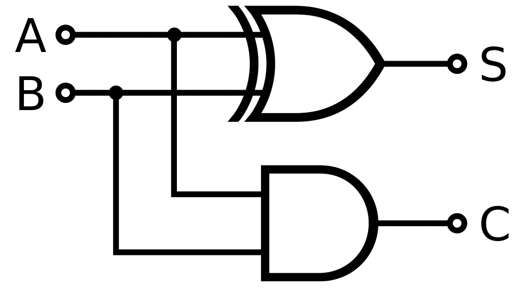
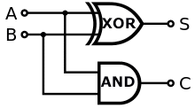
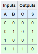
Below is the logic circuit for the simplest adder called a Half Adder. It can only add 2 binary numbers. We can form an input table with the outputs we want and see that the simple logic circuit below does this for us.
The above table has a row for every A and B input combination. S is the sum, so 0 + 0 must be 0, and 0 + 1 is just 1. Likewise, 1 + 0 is also 1. Finally, when we add 1 + 1 in binary, the total is 0 with a carry over of 1. You should review the binary article to under this important concept when adding binary numbers. When we have a carry, we represent this in the C column. Only 1 + 1 has a carry. In normal base 10 addition, you would carry the 1 when anything goes over 9.
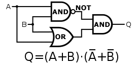
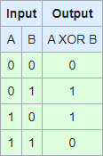
The circuit uses the XOR gate or more formally, Exclusive OR. XOR gates are 1 when just one input is 1. 0 XOR 1 is one, but 1 XOR 1 is zero since it has more than 1 one input. Below is the logic circuit for it using basic AND, OR, and Inverter gates that we can build using electronic components.
The round circle after the AND gate inverts the output. You should trace a signal to verify that the logic only gives 1 for inputs 0/1 and 1/0.
Being able to just add two bits may not seem useful, but we will see in part two of this article that we can string an unlimited number of half adders together to allow any size number, such as 1101010 + 1001011.
We actually covered a lot of material, so take some time to really understand this important concept and watch the logic gate video.
Here is a fun video showing how you can build simple gates with dominoes. This means you could also build our half-adder out of them which we will leave as an exercise for you if you have the time and patience. You could even build a simple working computer out of just dominoes! The video below it gives a nice overview of the important XOR logic and half-adders.
")


")