
Hi guys! Today I ‘m going to tell you how to make a simple traffic light circuit without using a microcontroller. You’ll find this very interesting, especially if you’re a TECH LOVER, or a person who love electronics. Even if you’re not, you’ll need to try this!
Please let me know how your circuit went and if you have anything to ask regarding the project. Feel free to ask questions in the comment section of the article.
OK then… let’s goooooo!!!
First, I need to tell you what you’ll need and will later explain the reason.
Components needed:
| Component | Number of Units |
| 555 timer ICs | two |
| LEDs ~ red, yellow, green | one in each color (total 3) |
| Resistors | one of each: 100k, 47k, 470R, 220R (total 4) |
| Capacitors | two 100uF capacitors |
| Power Breadboard | PBB 272B, or Breadboard 1 |
| Jumper wire kit | one |
Let me explain more about the components needed.
You should use two 555 timer ICs. You can see a pic of it below: (I will be doing another post about IC’s for beginners of electronics). A 555 timer is used to send a steady electronic timing voltage pulse, such as one per second based on settings.

Next, you need some LEDs. We only need 1 red LED, 1 yellow LED, and 1 green LED.
Don’t get multi-color LEDs for this!
Next, we need resistors with the following values in Ohms: 100k (1), 0,47k (1), 470R (1) and, and 220R (2)
We need 2 capacitors of 100uF and a Power breadboard PBB 272B.
You can also buy a normal breadboard. We ‘re not using a solderable one. Just a solderless one.
Here is a pic of a PBB 272B.
(I’ll be doing a post about types of breadboards later)
We also need a jumper wire kit. We won’t use the whole kit, but you can buy the kit and use it for future circuits you make. Here you can see some pics of jumper wire kits:
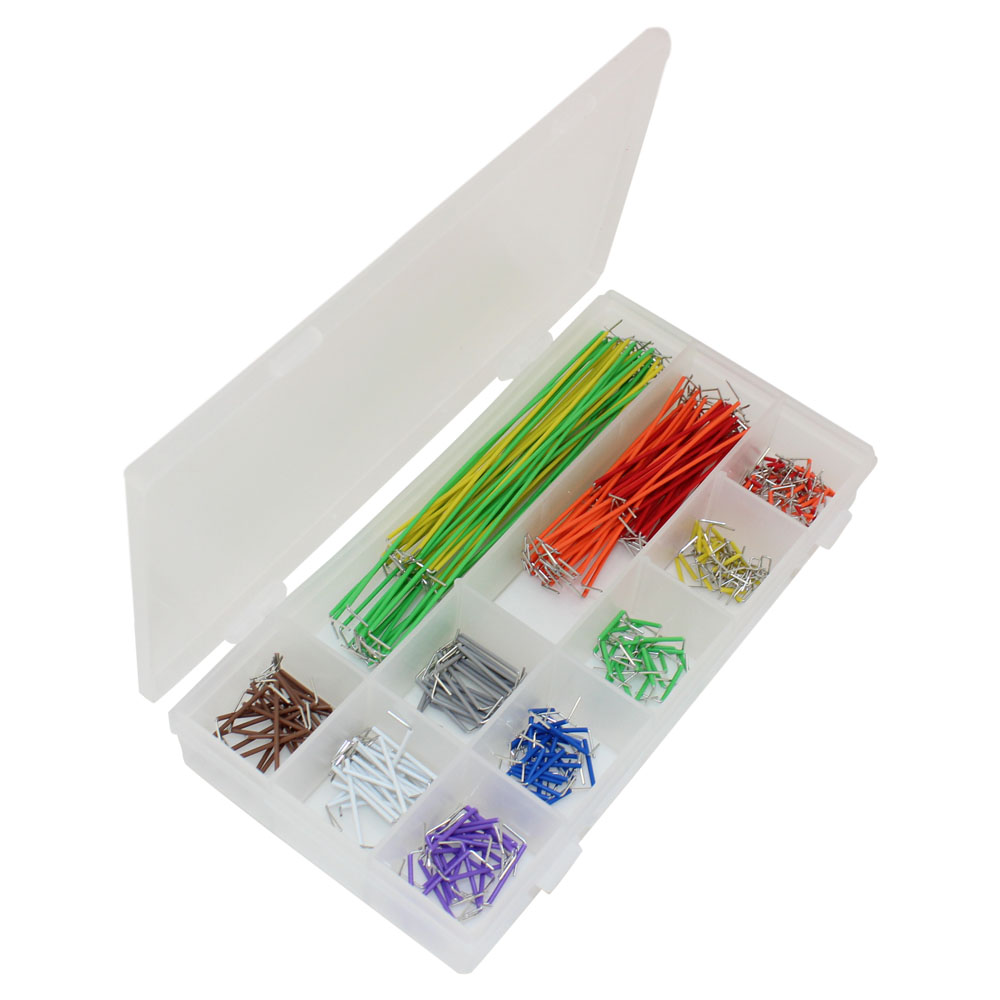 This (the box ) is the type of my kit.
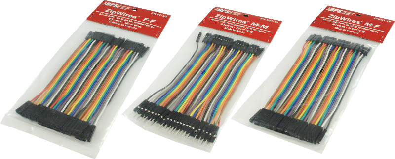 They are also sold like this, but I prefer the above top most one (my type).
Ok then here’s a detailed list of components you ‘ll need “with the parts”

I hope this will help you to identify the parts well. So let’s see the circuit diagram.

The above pic is the circuit diagram you should follow. I hope you’ll understand it. If you have any problems ask me in the comment section, or you can get help from your dad (or mom).
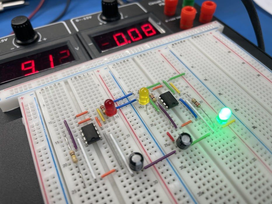
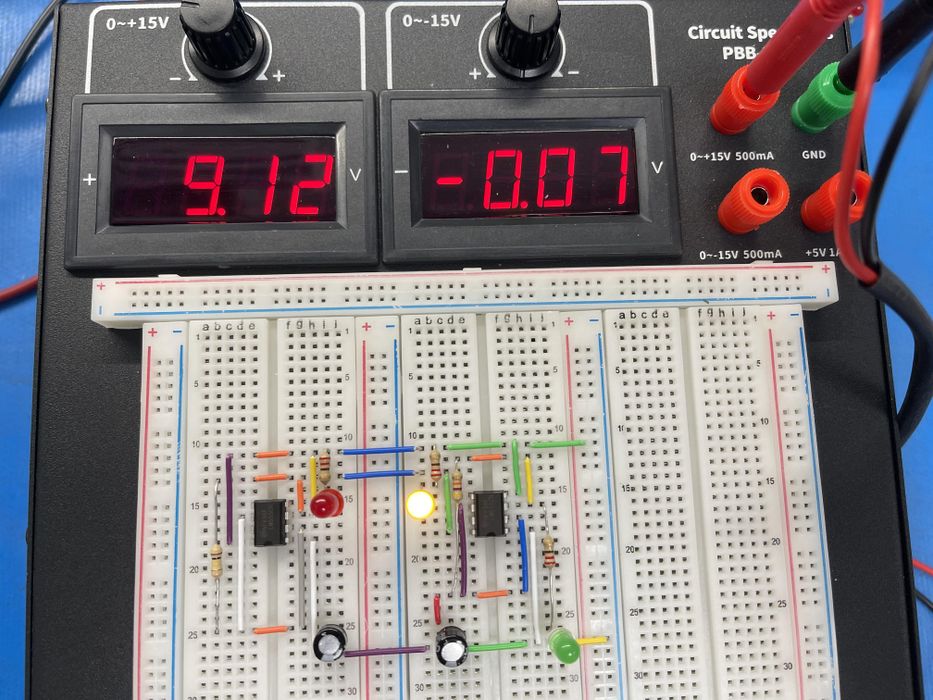
I used a solderless breadboard, which means we shouldn’t need to solder the components to it ( so you can make the circuit by yourself).
Fix the components on the breadboard and fix the jumper wires correctly (you can get help of your mom or dad if wanted)
NOW THE CIRCUIT IS READY!!!

Do you know how this circuit works ? Let’s find out!
First, let’s see how green cycle works.
After you power on this circuit, the 1st 555 timer IC will be in state ON coz the voltage at pin 3 (trigger pin) is less than 1/3 or voltage supply. The red LED can’t turn ON yet, but the 2nd IC is powered so the Green LED turns ON!!!
Then, let’s see how the yellow cycle works.
The capacitor of the 2nd 555 timer IC slowly starts charging , and as soon as it reaches 2/3 of the voltage supply, the output of the 2nd IC turns OFF and the yellow one glows because the discharge pin is activated. right?

Now let’s talk about the red cycle.
Normally, the yellow LED would turn ON for the same reason as the green one. but even before the capacitor of 2nd 555 timer IC reaches 1/3rd of the voltage supply, the voltage across the capacitor of first 555 timer IC reaches 2/3rds of the supply voltage, so the output of 1st 555 IC turns OFF, resulting in the yellow LED turning OFF, and the red LED turning ON. The Cycle repeats with Red On. OK?
Now I hope you have a better idea about how this works. If you have any questions please ask me in the comment section of this article. I’ll help you ASAP.
Here’s a link for a video that you can watch it. It’ll help you understand it more.
I’ll do more posts about electronics and plan to create an electronics group. Join it and find more circuits.
Ok then. Let me know how your circuit went and ask anything about it from me.
Thanks for all and KIDZSEARCH.
HAPPY DAY FRIENDS!!!
")
 -By Alex")
- By Alex")